The Engineering and Dynamics of Material Handling: How a Forklift Works
The forklift, or powered industrial truck, is a core piece of equipment in modern logistics, designed to lift, move, and stack heavy materials with precision and efficiency. Its seemingly simple operation is underpinned by a complex interplay of engineering principles, specifically hydraulic systems and fundamental physics of stability.
This technical article provides an in-depth analysis of the forklift's operational mechanism, detailing the major components, the function of its hydraulic power system, and the critical dynamic principles, such as the Stability Triangle, that govern safe operation.1
I. Major Structural and Power Components
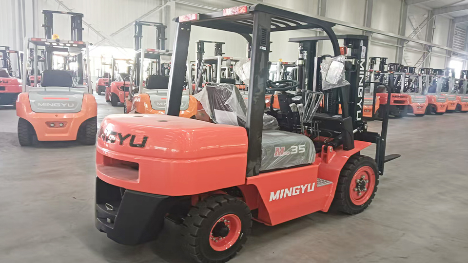
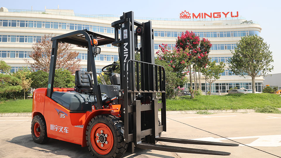
A typical counterbalanced forklift is an integrated system of several specialized components, all anchored to a heavy-duty frame.2
A. The Truck Frame (Chassis)
The Truck Frame forms the fundamental chassis of the machine, acting as the structural base to which all other components—including the mast, axles, wheels, and power source—are mounted.3 It is designed to handle the massive static and dynamic loads generated during lifting and travel. In many models, the fuel or hydraulic fluid reservoirs are integrated into the frame assembly.4
B. The Counterweight
The Counterweight is a critical, heavy cast-iron or steel mass attached to the rear of the truck frame.5 Its sole purpose is to counterbalance the heavy load carried on the forks.6 The principle is one of mechanical leverage: the counterweight's mass, acting at a distance behind the front axle (the fulcrum), generates a moment that opposes the moment created by the load in front of the axle.7 In electric forklifts (Class I), the large battery pack often serves as a significant part of the counterweight mass.8

C. The Power Source
Forklifts are powered either by Internal Combustion (IC) engines (fueled by LP gas, CNG, gasoline, or diesel) or by Electric Motors (powered by large lead-acid or lithium-ion battery packs, or fuel cells).9
IC Engines are typically used for high-capacity, outdoor, or continuous-operation applications.
Electric Motors are preferred for indoor applications (warehouses, food processing) due due to their zero local emissions, lower noise profile, and immediate high torque.10 The electric power unit drives both the traction motors and the hydraulic pump motor.
D. Axle and Steering Configuration
Unlike automobiles, most forklifts utilize rear-wheel steering.11 The steer axle is at the rear and is attached to the frame by a pivot pin at its center, allowing the rear end to swing for a tight turning radius.12 The drive axle, located at the front, provides the power for motion.13 This inverted steering configuration requires a specific operational awareness, as the rear end swings wide during turns.14
II. The Hydraulic Lifting and Tilting System
The ability of a forklift to lift and position heavy loads is achieved through a robust hydraulic system that operates on Pascal's Law—pressure applied to a confined fluid is transmitted equally in all directions throughout the fluid.15
A. Core Hydraulic Components
Hydraulic Fluid Reservoir (Sump): Stores the hydraulic oil (usually petroleum-based, water-based, or synthetic fluid).16
Hydraulic Pump: Driven by the forklift’s engine or a separate electric motor, the pump draws fluid from the reservoir and generates continuous high-pressure flow (often exceeding 17$2,000 \text{ psi}$ and sometimes reaching 18$10,000 \text{ psi}$) into the system lines.19
Control Valves: Operated by the levers in the cab, these valves direct the flow and pressure of the hydraulic fluid to the various actuators (cylinders) for the lift, tilt, and any auxiliary functions (e.g., side-shift).20
Hydraulic Cylinders: These are the mechanical actuators that convert fluid pressure into linear force.21
Lift Cylinders: Large, single-acting ram-type cylinders that receive high-volume flow.22 Pressurized fluid pushes the piston/rod outward to raise the mast. Gravity and the load's weight facilitate the controlled lowering when the pressure is released via the control valve.
Tilt Cylinders: Typically smaller, double-acting piston-type cylinders mounted near the frame base.23 They allow fluid to be pressurized on either side of the piston, enabling the mast to tilt forward (for depositing a load) and backward (for stabilizing a carried load).24
B. The Mast and Chain-Over-Sheave System
The Mast is the vertical assembly that lifts and lowers the load.25 It consists of interlocking rails (channels) guided by rollers or bushings. The vertical movement of the forks is often achieved using a chain-over-sheave (pulley) system driven by the lift cylinders.26
Cylinder Movement: When the operator engages the lift lever, pressurized fluid extends the lift cylinder rod upward.27
Chain Mechanism: The top of the lift cylinder is typically connected to a sheave (pulley). A roller chain is anchored to the stationary mast frame at one end, wraps around the sheave, and is then connected to the carriage (the platform holding the forks) at the other end.
Mechanical Advantage: When the cylinder extends its rod by a distance $L$, the sheave moves upward. Because of the chain reeving (wrapping) around the sheave, the carriage and the forks are forced to move upward by a distance that is twice the extension of the cylinder rod ($2L$). This arrangement provides a crucial mechanical advantage, allowing the forks to lift much higher than the physical stroke of the cylinder, and enabling multi-stage (duplex, triplex, quad) masts.
III. The Principle of Stability: The Stability Triangle
The most critical technical aspect of forklift design and operation is its stability, which is governed by the principle of the Stability Triangle.28 Unlike an automobile, a forklift is constantly balancing a dynamic, cantilevered load that is external to its footprint.29
A. Defining the Stability Triangle
The Stability Triangle is an imaginary three-point support system that defines the forklift's zone of stability at ground level.30 It is formed by connecting:
The center of the Front-Left Wheel (load axle pivot point).
The center of the Front-Right Wheel (load axle pivot point).
The Pivot Point at the center of the Rear (Steer) Axle.31
For the forklift to remain stable—to prevent either a forward/backward or lateral tip-over—the Combined Center of Gravity (CCG) of the forklift and its load must remain within the perimeter of this triangle.32

B. The Combined Center of Gravity (CCG)
The CCG is a constantly shifting point, calculated as a vector sum of the forklift's unladen center of gravity (usually near the counterweight) and the load's center of gravity.33
Unloaded: The CCG is close to the center of the machine, low to the ground, and well within the triangle.
Loaded (Travel Position): When a load is placed on the forks, the CCG shifts forward and outward, closer to the front axle (the fulcrum).34
Loaded (Lifted High): When the load is raised, the CCG also shifts upward and further forward.35 This reduces the margin of stability, effectively transforming the 2D Stability Triangle into a 3D Stability Pyramid.
The maximum safe load (Rated Capacity) is determined by engineering calculations that ensure the CCG remains within the Stability Triangle's boundaries under standard operating conditions (e.g., a Load Center of 24 inches is standard for capacity rating).36 Exceeding the rated capacity or increasing the load center (the horizontal distance from the carriage to the load’s center of gravity) moves the CCG beyond the front line of the triangle, leading to an immediate longitudinal tip-over (forward).37
C. Stability Types and Dynamic Forces
Safe operation requires maintaining three types of stability:
Longitudinal Stability (Front-to-Back): Governed by the counterbalance principle.38 It is lost when the load moment overcomes the counterweight moment, shifting the CCG forward out of the triangle.
Lateral Stability (Side-to-Side): Governed by the width of the triangle's base. It is lost due to dynamic forces created by turning at speed, traveling on uneven ground, or tilting the mast too far forward while the load is raised.
Dynamic Stability: The susceptibility of the CCG to shift due to motion.39 Sudden braking shifts the CCG forward. Sudden acceleration shifts the CCG backward. Sudden turning shifts the CCG laterally.40 These dynamic shifts are why operators are trained to:
Keep the load as low as possible (4–6 inches off the ground) during transit.41
Tilt the mast fully backward (back-tilt) while traveling to pull the CCG back toward the counterweight.42
Avoid sudden movements, especially when the load is elevated.43
IV. Conclusion and Operational Parameters
The efficiency and safety of a forklift are the direct result of precision engineering that marries powerful hydraulics with meticulous adherence to the physics of leverage and balance. The forklift is not merely a vehicle; it is a lever system designed to manipulate extreme weights in a confined space. Its working mechanism depends on the operator’s technical understanding of its structural limits, particularly the dynamic nature of the Combined Center of Gravity relative to the fixed boundary of the Stability Triangle. Compliance with the rated capacity, load center, and operating guidelines remains the non-negotiable factor in preventing catastrophic mechanical and safety failures.44
Name: selena
Mobile:+86-13176910558
Tel:+86-0535-2090977
Whatsapp:8613181602336
Email:vip@mingyuforklift.com
Add:Xiaqiu Town, Laizhou, Yantai City, Shandong Province, China