
vip@mingyuforklift.com
+86-0535-2090977

��️ How Many Control Arms Does a Clamp Forklift Have? A Technical Analysis of Hydraulic Workgroup and Attachment Control
The question of "how many control arms does a clamp forklift have?" is fundamentally a question of hydraulic circuit design and operator interface ergonomics specific to the truck's operational functions. Unlike a standard counterbalanced forklift equipped only with lift and tilt controls, a clamp forklift requires dedicated hydraulic action to open, close, and often rotate the clamp attachment itself.
A conventional, internal combustion or electric, counterbalanced forklift typically has two to three primary control levers dedicated to the workgroup: one for lift/lower, one for mast tilt (forward/back), and often a third for the sideshift function. However, the addition of a clamping attachment requires at least one or two additional dedicated control mechanisms to manage the clamp's movement.
This technical article will dissect the hydraulic and mechanical systems of a clamp forklift, analyzing the required control functions, their physical manifestation as operator control arms, and the design factors that determine the final number and type of controls in a modern industrial truck.
I. Defining the Clamp Forklift Workgroup
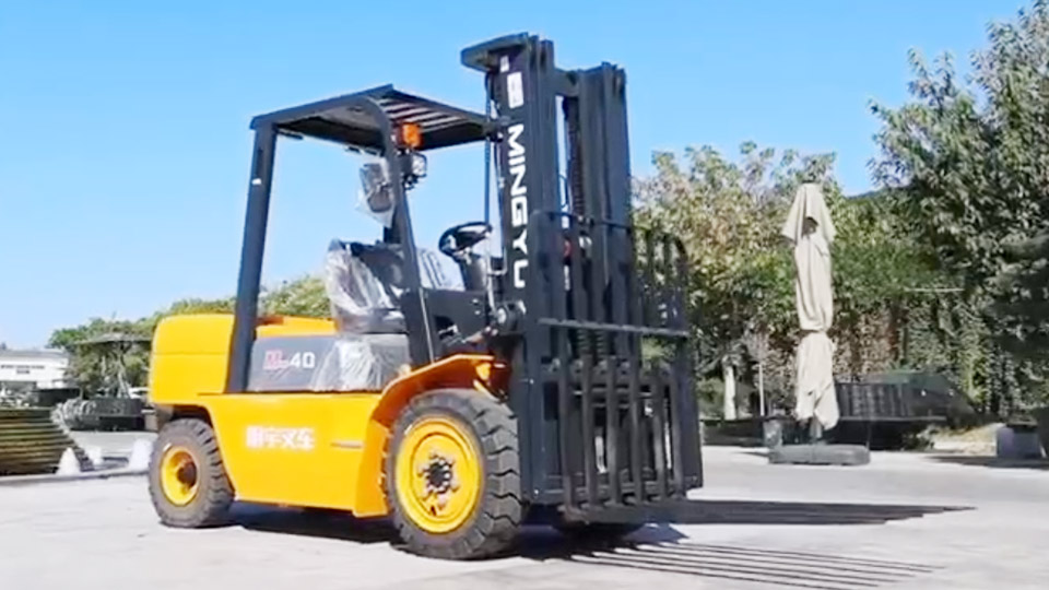
A clamp forklift is an industry-specific configuration achieved by replacing standard forks with a specialized hydraulic attachment. This configuration is often used for handling cylindrical goods (paper rolls, barrels), square/rectangular bales (cotton, pulp), or appliances, which require lateral clamping pressure rather than underside fork support.
1.1. The Basic Three-Function Standard Truck
Before adding the clamp, the base forklift must be equipped with hydraulic circuits for its essential functions:
Lift/Lower: Controls the vertical movement of the carriage and load.
Tilt: Controls the fore-and-aft angle of the mast (and therefore the attachment) for stability.
Sideshift (Standard Third Function): Controls the lateral movement of the carriage for precise load positioning.1
These three functions are typically controlled by the first three levers or buttons on the operator's right-hand console.
1.2. The Clamp Attachment Requirement
A fully functional clamp attachment requires at least one additional hydraulic function and often a second, leading to four or five total functions that require operator control:
Function 4 (Clamp/Unclamp): This is the mandatory circuit that controls the primary action—moving the clamp arms inward (closing/clamping) and outward (opening/unclamping). This requires a two-way (double-acting) hydraulic cylinder.
Function 5 (Rotation): Many clamps, particularly specialized paper roll clamps, must be able to rotate the load $90^\circ$ or $180^\circ$ to change orientation (e.g., from vertical storage to horizontal loading). This requires a fifth hydraulic function.
Therefore, a standard clamp forklift, depending on its complexity, will require four or five hydraulic control circuits dedicated to load manipulation.
II. Control Arm Configuration: The Physical Interface
The number of physical control arms (levers) an operator sees is directly correlated with the number of hydraulic circuits installed and the ergonomic system chosen by the manufacturer (e.g., Komatsu, Hyster, Toyota, Crown).
2.1. The Traditional Mechanical Lever System
In older or simpler clamp trucks, each hydraulic function is controlled by a dedicated, mechanical spool valve connected to a steel lever (control arm).
|
Hydraulic Function |
Required Control Arm |
Total Control Arms |
|
Lift/Lower |
Arm 1 |
1 |
|
Tilt |
Arm 2 |
2 |
|
Sideshift |
Arm 3 |
3 |
|
Clamp/Unclamp |
Arm 4 |
4 |
|
Rotation (Optional) |
Arm 5 |
5 |
Under the traditional mechanical lever system, a typical clamp forklift will therefore have four (minimum) to five control arms in total. Each arm is physically connected to a hydraulic control valve spool, allowing the operator to meter the fluid flow to the corresponding cylinder.
2.2. Ergonomic Evolution: Joysticks and Fingertip Controls
In modern trucks, manufacturers have moved away from multiple, large levers to improve ergonomics and speed. This change affects the physical manifestation of the control, but not the number of required hydraulic circuits.
Mini-Levers (Fingertip Controls): The most common modern arrangement uses small, low-effort levers often integrated into the armrest. The clamp/unclamp function is typically assigned to the fourth lever in this row. A fifth lever is added for rotation. The total number of separate fingertip controls remains four or five.
Integrated Joystick: Some advanced trucks use a single multi-function joystick for the primary functions (Lift/Lower and Tilt). The secondary functions (Sideshift, Clamp, and Rotation) are then delegated to dedicated buttons or mini-levers clustered on the joystick head or armrest.
Crucial Insight: The number of required control signals (four or five) remains constant, regardless of whether those signals are generated by large mechanical levers, mini-levers, or electronic buttons/joysticks. When discussing "control arms," one must specify whether they mean the traditional levers or the dedicated control mechanisms. In the context of traditional arms, the number is four to five.
III. The Hydraulic Circuit and Valve Block
Understanding the control arms requires a look at the hydraulic heart of the system—the valve block.
3.1. The Directional Control Valve (DCV)
Every function is governed by a separate section of the DCV, also known as the spool valve. Each section is designed to direct pressurized hydraulic fluid (2$P$) from the pump to the required cylinder or motor, and return fluid (3$R$) to the reservoir.4
The clamp and rotation functions require double-acting cylinders or motors:
$$\text{Double-Acting Cylinder} \rightarrow \text{Fluid required to extend (Clamp) and retract (Unclamp)}$$
Each function section within the DCV stack is called a spool. Therefore, a clamp forklift requires a DCV with at least four spools (Lift, Tilt, Sideshift, Clamp) and five spools if rotation is included. Each spool must be connected to an operator control mechanism.
3.2. Hydraulic Flow and Priority
The placement and function of the control arms are often determined by the need for hydraulic priority.
Primary Functions (Lift/Tilt): These are typically placed closest to the operator and are often directly linked to the highest pressure and flow circuits.
Auxiliary Functions (Clamp/Sideshift/Rotation): These are typically controlled by the third, fourth, and fifth control arms. They often operate at slightly lower pressures or flows, as they require less power than lifting a multi-ton load. In the case of clamping, precise flow control is vital to avoid crushing the load, hence the need for a dedicated, metered control arm.
3.3. 4-Way vs. 6-Way Hydraulics
The technical specification of the truck will describe the number of hydraulic functions supported:
3-Way: Lift, Tilt, Sideshift.
4-Way: Lift, Tilt, Sideshift, Clamp/Unclamp. (This is the minimum required for a basic clamp truck.)
5-Way: Lift, Tilt, Sideshift, Clamp/Unclamp, Rotation. (Common for paper roll clamps.)
6-Way: Allows for specialized attachments like articulating clamps or multiple clamp arms, requiring six total control arms/signals.
Therefore, the standard clamp forklift is a 4-way or 5-way hydraulic machine, requiring a corresponding number of operator controls.
IV. Clamp Arm Configuration: The Attachment Design
While the operator controls the overall clamp, the attachment itself can have various arm configurations, which is separate from the number of control arms.
4.1. Single Pair Clamps (Two Arms)
Most common clamps (paper roll, bale, carton) use a single pair of arms that move symmetrically relative to the center of the load.
Control Arm Count: One dedicated control arm (the 4th function) controls both arms' symmetrical movement. The hydraulic fluid is metered equally to the cylinders controlling the movement of each arm.
4.2. Split-Arm or Multiple-Arm Clamps
Some specialized attachments, particularly those designed for handling large stacks of goods or different sized rolls simultaneously, may utilize independent or differential arm movement.5
Independent Arm Control: In highly specialized systems (e.g., dual paper roll clamps), the operator may need the ability to clamp one roll before the other. This setup would require two separate hydraulic circuits for clamping—one for the left arm and one for the right arm.
Control Arm Count: This specialized design would push the required control count to five or six total controls (3 standard + 2 independent clamps + 1 rotation), requiring two separate control arms for the clamping function alone. This level of complexity is rare, however, and is reserved for bespoke, high-volume operations.
For the purpose of answering the general question, the vast majority of industrial clamp trucks use a single control arm (the 4th) to symmetrically manage a single pair of clamp arms.
V. Operator Safety and Ergonomic Considerations
The number and placement of control arms are also critical safety and ergonomic features governed by standards like ANSI/ITSDF B56.1.
5.1. Intuitive Design
Controls must be clearly labeled and positioned logically. The hydraulic function most frequently used—clamping—should be placed in a convenient and intuitive position, typically as the next lever after the primary lift/tilt controls.
5.2. Safety Interlocks
The clamp control arm is often subject to safety considerations, though this does not change the number of arms.
Regulated Pressure: The hydraulic system must be equipped with a pressure relief valve dedicated to the clamp circuit.6 This prevents the operator from applying excessive clamping force that could crush the load (e.g., a paper roll) or over-stress the attachment, regardless of how forcefully the control arm is actuated.7
Audible Warnings: Actuating the clamp control arm may trigger an audible warning (e.g., a "clamp close" chime) to alert nearby personnel, a requirement driven by operational safety protocols, not the control arm count itself.
5.3. Return to Neutral
All modern control arms/levers are designed with a spring-return-to-neutral feature. When the operator releases the control arm for clamping or unclamping, the lever must immediately return to the center (neutral) position, stopping the hydraulic flow and locking the clamp pressure in place until the lever is re-actuated. This is a safety mechanism inherent to the control arm's design.
VI. Conclusion: The Definitive Count
The question of how many control arms a clamp forklift has moves beyond a simple numerical answer and into an analysis of its hydraulic engineering.
The minimum and most common number of operator control arms (levers/mini-levers) for a standard industrial clamp forklift is four.
Lift/Lower
Tilt (Mast Angle)
Sideshift (Lateral Positioning)
Clamp/Unclamp (Attachment Operation)
For applications requiring load orientation, such as handling paper rolls or specialized boxes, a fifth control arm is added:
Rotation (Horizontal/Vertical Load Turning)
Therefore, while the mechanical components of the base truck require only two arms (Lift/Tilt), the necessity of dedicated hydraulic metering for load manipulation adds at least one (for clamping) and often two (for clamping and rotation), bringing the total number of dedicated control arms to four or five. This configuration ensures the operator has the precise, independent control necessary to safely manage the load, the attachment, and the forklift's primary functions simultaneously.
Summary of Control Arm Requirements
|
Function |
Hydraulic Requirement |
Control Arm Count (Traditional) |
|
Lift/Lower |
Primary Flow |
1 |
|
Tilt |
Primary Flow |
1 |
|
Sideshift |
Auxiliary Flow |
1 |
|
Clamp/Unclamp |
Dedicated 4th Function |
1 |
|
Rotation |
Dedicated 5th Function |
1 (Optional) |
|
Total |
4 or 5 Hydraulic Circuits |
4 (Minimum) to 5 (Standard) |
This technical requirement, whether implemented via traditional levers or modern electronic fingertip controls, defines the operational complexity and functionality of the clamp forklift workgroup.
Name: selena
Mobile:+86-13176910558
Tel:+86-0535-2090977
Whatsapp:8613181602336
Email:vip@mingyuforklift.com
Add:Xiaqiu Town, Laizhou, Yantai City, Shandong Province, China
