
vip@mingyuforklift.com
+86-0535-2090977

Introduction: The Critical Interface Between Machine and Load
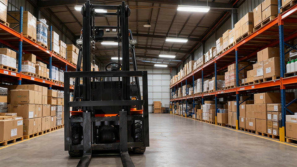
In the complex mechanical architecture of material handling equipment, the forklift carriage represents one of the most consequential yet frequently misunderstood components. While operators and facility managers readily identify masts, forks, and counterweights as essential forklift elements, the carriage—the vertical sliding assembly that connects the mast to the forks—often receives insufficient attention despite its fundamental role in load stability, attachment versatility, and operational safety.
The carriage serves as the critical mechanical interface that translates hydraulic lifting force into vertical load movement while providing standardized mounting points for forks and specialized attachments. Understanding carriage design, classification standards, and operational parameters is essential for proper equipment specification, attachment selection, and maintenance protocols. This article provides a detailed technical examination of forklift carriage systems, their engineering principles, standardization frameworks, and practical implications for warehouse operations.
Defining the Forklift Carriage: Functional Architecture
Primary Functions and Mechanical Role
The forklift carriage performs three essential mechanical functions that enable material handling operations. First, it serves as the vertical translation mechanism, converting the linear extension of hydraulic lift cylinders into controlled upward and downward movement of loads. The carriage assembly rides within the mast channels on roller or slider bearings, maintaining precise alignment while supporting dynamic loads that may exceed 50,000 pounds in heavy-duty applications.
Second, the carriage provides the structural mounting interface for load-handling attachments. Through standardized hook-type or shaft-mounted connections, the carriage enables rapid fork repositioning and attachment exchange without requiring specialized tools or extended downtime. This modularity distinguishes industrial forklifts from fixed-lifting equipment and enables the operational versatility that characterizes modern material handling.
Third, the carriage integrates load backrest structures that stabilize elevated loads and protect the mast assembly from damage. The backrest—typically comprising vertical uprights and horizontal bracing—prevents palletized loads from shifting rearward during acceleration, braking, or mast tilting operations, thereby protecting hydraulic cylinders, hoses, and the operator cab from impact damage.
Structural Components and Assembly
A complete carriage assembly comprises several engineered subcomponents. The carriage bars (also termed carriage plates or uprights) form the primary vertical structural elements, manufactured from high-strength steel plate typically ranging from 0.75 to 2 inches in thickness depending on capacity ratings. These bars incorporate upper and lower hook points for fork engagement, mounting interfaces for the load backrest, and bearing surfaces for mast channel engagement.
The carriage rollers or slider blocks facilitate vertical movement within the mast channels. Roller configurations utilize sealed bearing assemblies mounted on hardened shafts, while slider configurations employ ultra-high molecular weight (UHMW) polyethylene or bronze wear plates that slide directly against mast channel surfaces. Roller designs predominate in higher-capacity applications due to reduced friction and improved efficiency under heavy loads.
Side shift mechanisms, when integrated into the carriage assembly, enable lateral fork movement (typically 4–6 inches in either direction) without requiring vehicle repositioning. These mechanisms employ hydraulic cylinders mounted within the carriage structure, adding 200–400 pounds to assembly weight while significantly improving load placement precision in tight racking configurations.
Carriage Classification Standards: ISO and ITA Specifications
ISO 2328 and Forklift Carriage Standardization
The International Organization for Standardization establishes dimensional and capacity specifications for forklift carriages through ISO 2328, which defines hook-type fork carriers and fork engaging devices. This standardization ensures interoperability between forklift manufacturers and attachment suppliers, enabling end-users to source compatible equipment across diverse equipment fleets.
ISO 2328 classifies carriages by carriage height—the vertical distance between upper and lower hook points—and carriage width, establishing five primary classes that correspond to forklift capacity ranges. Standardization of hook spacing, hook geometry, and engagement depth ensures that forks manufactured by any ISO-compliant supplier will properly engage carriages produced by any equipment manufacturer adhering to the standard.
ITA Carriage Classes: The Industry Framework
The Industrial Truck Association (ITA) carriage classification system provides the most widely referenced framework in North American markets. ITA defines five carriage classes based on vertical hook spacing and rated load capacities:
Class I carriages accommodate forklifts with capacities up to 2,000 pounds, featuring hook spacing of 13 inches. These compact carriages serve specialized applications including narrow-aisle reach trucks and pallet jacks where space constraints limit component dimensions.
Class II carriages cover the 2,000–5,500-pound capacity range with 16-inch hook spacing. This class represents the most common carriage specification in warehouse environments, serving standard electric and internal combustion forklifts deployed in distribution centers and manufacturing facilities.
Class III carriages address medium-duty applications from 5,500–10,000 pounds, utilizing 20-inch hook spacing. The increased vertical dimension accommodates larger fork cross-sections and heavier attachment mounting structures required for steel, lumber, and beverage handling operations.
Class IV carriages serve heavy-duty applications from 10,000–17,500 pounds with 25-inch hook spacing. These robust assemblies incorporate thicker carriage bars, larger diameter rollers, and reinforced hook geometries to manage the extreme loads encountered in paper mills, metal service centers, and port operations.
Class V carriages accommodate capacities exceeding 17,500 pounds, featuring 28.625-inch hook spacing. These specialized assemblies often incorporate custom engineering for specific applications, though ITA standards maintain sufficient dimensional consistency to enable fork interchangeability within the class.
Metric Classifications and Global Variations
European and Asian markets frequently reference metric carriage classifications based on hook spacing in millimeters. Common specifications include 400mm, 500mm, and 600mm carriages that roughly correspond to ITA Classes II, III, and IV respectively. Global equipment manufacturers typically offer both imperial and metric carriage configurations to serve diverse market requirements, with some manufacturers producing dual-configuration carriages that accommodate both standard sets through adjustable hook mechanisms.
Carriage Design Variations and Specialized Configurations
Hook-Type vs. Shaft-Mounted Fork Attachments
The predominant carriage design utilizes hook-type fork attachment, where fork heels incorporate upper and lower hooks that engage corresponding hooks on the carriage bars. This configuration enables rapid manual fork repositioning and replacement, with typical engagement requiring only vertical alignment and rearward insertion until locking mechanisms engage.
Shaft-mounted configurations (also termed pin-type or bar-type mounting) utilize horizontal shafts welded to the carriage bars, with forks incorporating cylindrical receivers that slide over these shafts. This design distributes load stresses more evenly across fork cross-sections and eliminates the stress concentrations associated with hook geometries. Shaft mounting predominates in applications involving extreme load cycling, heavy shock loading, or specialized attachments requiring rigid mounting interfaces.
Integral Carriage and Mast Designs
Reach trucks and narrow-aisle forklifts frequently employ integral carriage designs where the carriage structure and mast inner channels form a unified assembly. In these configurations, the reach mechanism extends the entire mast carriage assembly forward, eliminating the clearance requirements of traditional roller carriages and enabling operation in aisles as narrow as 6 feet. The integrated design sacrifices some attachment versatility for compact dimensions and enhanced stability in high-reach applications.
Side-Shifting and Fork-Positioning Carriages
Integrated side shift carriages incorporate hydraulic lateral movement mechanisms within the carriage structure, enabling precise fork alignment with pallet openings without vehicle repositioning. These assemblies replace standard carriages and require hydraulic supply lines routed through the mast structure, adding complexity but significantly improving operational efficiency in high-density storage applications.
Fork positioner carriages extend this concept by enabling hydraulic adjustment of fork spacing (the horizontal distance between forks). Rather than manually repositioning forks along the carriage width, operators adjust spacing via hydraulic controls, dramatically reducing load handling time when processing diverse pallet sizes. These carriages add 300–600 pounds to vehicle weight and reduce effective load capacity proportionally, but improve productivity sufficiently to justify the investment in multi-SKU distribution environments.
Load Backrest Integration and Design
Structural Functions and Safety Requirements
The load backrest mounted to the carriage serves critical safety and equipment protection functions. OSHA regulations mandate backrests for forklifts handling loads that could fall rearward onto the operator or vehicle components, effectively requiring backrests on virtually all counterbalance forklifts in industrial service.
Backrest heights typically range from 36 to 60 inches above the fork plane, with height selection based on expected load dimensions. Standard 48-inch backrests accommodate typical palletized loads stacked to 60-inch heights, while extended 60-inch or 72-inch backrests serve applications involving tall, unstable loads such as appliances, paper rolls, or stacked sheet materials.
Backrest-to-Carriage Attachment Interfaces
Backrests attach to carriage assemblies through bolted or welded interfaces. Bolted configurations enable backrest replacement when damage occurs or when application requirements change, while welded configurations provide maximum rigidity for extreme service conditions. Some carriage designs incorporate integrated backrest structures where the backrest uprights extend downward to form the carriage bars themselves, eliminating separate attachment points and reducing overall assembly weight.
Carriage Maintenance and Wear Management
Roller and Bearing Maintenance
Carriage rollers operate under extreme load conditions, with individual rollers on heavy-duty forklifts supporting dynamic loads exceeding 10,000 pounds during acceleration and braking cycles. Maintenance protocols must include regular inspection of roller bearings for seal integrity, lubricant condition, and rotational smoothness.
Worn rollers manifest as mast channel damage, erratic vertical movement, or increased hydraulic system pressure requirements. Replacement rollers must match original specifications for diameter, load rating, and bearing type—mixing roller specifications within a carriage assembly creates uneven load distribution and accelerates component failure.
Wear Plate and Slider Block Replacement
Slider block configurations require periodic replacement as wear progresses. UHMW polyethylene blocks typically service 2,000–4,000 operating hours before replacement, depending on load severity and environmental conditions. Bronze slider blocks offer extended service life but require lubrication maintenance and more frequent inspection for galling or adhesion to mast channel surfaces.
Hook Wear and Inspection Standards
Carriage hooks experience wear through repeated fork engagement and disengagement, particularly in applications requiring frequent fork changes or attachment exchanges. Inspection protocols must verify hook geometry compliance with manufacturer specifications, checking for spreading, cracking, or wear that could permit accidental fork disengagement.
ANSI B56.1 standards require annual inspection of load handling attachments including carriage hooks, with documentation requirements for maintained fleets. Hooks showing wear exceeding 10% of original dimension or evidence of cracking must be replaced immediately—repair welding of carriage hooks is prohibited due to the critical safety functions these components perform.
Operational Considerations and Attachment Compatibility
Load Center Calculations and Carriage Influence
Forklift capacity ratings assume specific load center distances—typically 24 inches for standard counterbalance forklifts. The carriage assembly contributes to effective load center calculations, as carriage weight positioned forward of the mast fulcrum point effectively reduces available load capacity. Heavy side-shift carriages or specialized attachment carriages may shift the effective load center forward by 2–4 inches, requiring capacity derating to maintain stability margins.
Attachment Interface Standardization
The carriage hook interface enables rapid attachment exchange, supporting operational versatility through clamps, rotators, push-pull devices, and specialized handling tools. However, attachment compatibility requires verification of carriage class, hook spacing, and hydraulic capacity (for powered attachments). Mismatched attachments—such as Class III forks on Class II carriages—create hazardous conditions including fork disengagement, structural overload, and stability compromise.
Advanced Carriage Technologies and Future Developments
Integrated Load Sensing and Weighing
Emerging carriage designs incorporate integrated load cells within the carriage structure, providing real-time weight indication without separate scale systems. These smart carriages enable immediate overload detection, inventory tracking integration, and shipping weight verification during the normal course of material handling operations.
Automated Attachment Recognition
Radio-frequency identification (RFID) and optical recognition systems mounted on carriage assemblies enable automatic attachment identification and parameter adjustment. When forks or specialized attachments engage the carriage, control systems automatically adjust hydraulic pressure limits, travel speed restrictions, and stability control parameters to match the specific attachment characteristics.
Conclusion: The Central Role of Carriage Design in Material Handling
The forklift carriage, while seemingly a simple structural component, embodies sophisticated engineering that enables the versatility, safety, and efficiency characterizing modern material handling operations. From standardized hook geometries that ensure global equipment interoperability to integrated hydraulic systems that enhance operational precision, carriage design directly impacts warehouse productivity and safety outcomes.
Understanding carriage classifications, maintenance requirements, and operational limitations enables informed equipment specification and fleet management decisions. As material handling automation advances and load sensing technologies mature, the carriage will continue evolving from passive structural component to intelligent system element—maintaining its central role as the critical interface between lifting machinery and the loads that drive global supply chains.
For equipment operators, maintenance technicians, and facility managers, comprehensive knowledge of carriage systems represents essential technical competency in the complex domain of industrial material handling.
Name: selena
Mobile:+86-13176910558
Tel:+86-0535-2090977
Whatsapp:8613181602336
Email:vip@mingyuforklift.com
Add:Xiaqiu Town, Laizhou, Yantai City, Shandong Province, China
