
vip@mingyuforklift.com
+86-0535-2090977

What is the Load Center on a Forklift? A Technical Deep Dive into Stability and Capacity
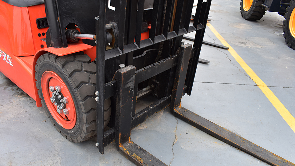
The load center (LC) is arguably the most critical variable an operator must understand to ensure the safe and effective operation of a forklift. It is the defining dimensional parameter that dictates the machine's safe rated capacity.1 In simple, technical terms, the load center is defined as the horizontal distance measured from the vertical face of the forks (the load-engaging surface of the carriage) to the load’s geometric center of gravity (CG).2
This article will explore the physical principles of the load center, its standardization, its relationship with the Stability Triangle and Load Moment, and the essential calculations required to de-rate capacity for non-standard loads.
I. Defining the Load Center and the Standard Rating
A. The Core Definition
According to the Occupational Safety and Health Administration (OSHA) and industry standards (such as ANSI/ITSDF B56.1), the load center is the horizontal measurement from the front face of the fork shank to the point where the entire weight of the load is considered to be concentrated.3
For a perfectly uniform, symmetrical, and cubic load placed flush against the fork carriage, the center of gravity lies precisely at the load's geometric center.4 Therefore, the load center is simply half the length of the load.5
$$\text{LC} = \frac{\text{Load Length}}{2}$$
B. The Industry Standard: 24 Inches (600 mm)
The majority of industrial counterbalanced forklifts are rated using a standard load center of 24 inches (600 mm).6
This standard is based on the common dimensions of a 48-inch x 48-inch (1200 mm x 1200 mm) pallet.7 If a uniform load is placed squarely on this pallet, its center of gravity is 24 inches from the front face.8
The manufacturer determines the forklift's maximum rated capacity (e.g., 5,000 lbs) at this specified 24-inch load center. This crucial information is stamped on the forklift's Data Plate (or Capacity Plate).9
Any deviation from this standard—specifically, an increase in the load center distance—will directly reduce the forklift's safe lifting capacity.10 This is the cornerstone of capacity de-rating, as explained by the Load Moment principle.
II. The Physics of Stability: Load Center, Fulcrum, and the Stability Triangle
A forklift operates on the principle of a first-class lever, also known as a seesaw.11 This mechanical relationship is key to understanding stability.
A. The Fulcrum and Counterbalance
On a standard counterbalanced sit-down forklift, the system pivots around a fixed point: the fulcrum.12
Fulcrum: This is the centerline of the front axle (the drive wheels).13 It acts as the pivot point separating the two forces.
Counterweight: The weight of the forklift chassis, engine/battery, and the heavy cast-iron or steel counterweight located at the rear of the machine. This is the balancing force.
Load: The weight of the material being lifted, plus the weight of the mast, carriage, and forks. This is the overturning force.
For the forklift to remain stable, the Load Moment (the overturning force) must be less than the Counterbalance Moment (the balancing force).
B. The Load Moment (Torque)
The load center's critical role is defined in the calculation of the Load Moment (14$M_{L}$).15 The Load Moment is the torque, or rotational force, being applied around the fulcrum (front axle).16
Torque is always the product of a force (weight) multiplied by the perpendicular distance from the pivot point (the lever arm).
$$M_{L} = \text{Load Weight} \times \text{Distance from Fulcrum}$$
When a manufacturer rates a forklift (e.g., 5,000 lbs at a 24-inch load center), they are stating the Maximum Allowable Load Moment (17$M_{\text{max}}$).18
$$M_{\text{max}} = \text{Rated Capacity} \times (\text{Rated LC} + \text{Distance from Axle to Fork Face})$$
Key Insight: Since the distance from the front axle to the face of the forks is a fixed physical property of the forklift, any increase in the Load Center (the distance from the face of the forks to the load's CG) acts to dramatically increase the Distance from the Fulcrum to the load’s CG.
This is why moving a load just a few inches further out exponentially increases the overturning force and reduces the safe capacity.
C. The Stability Triangle
Forklift stability is managed within the concept of the Stability Triangle . This is an imaginary geometric area that forms the base of the machine.
Rear Base: The center of the rear steer axle pivots on a single pin, which serves as the apex of the triangle.19
Front Base: The two ends of the front drive axle (the fulcrum points) form the base of the triangle.
For a forklift to remain stable and upright, the combined center of gravity (CCG)—the total CG of the forklift plus the load—must remain inside this imaginary triangle.20
Impact of Load Center: Increasing the horizontal load center (by lifting a longer load) or increasing the lift height (shifting the vertical load center) causes the CCG to shift forward and upward.21 If the CCG shifts forward and crosses the line of the front axle, the result is a catastrophic longitudinal tip-over (tipping forward).
Lateral Load Center: The load center also has a lateral (side-to-side) component. If the load is poorly distributed (e.g., heavier on one side of a pallet) or if the forks are unevenly spaced, the CCG shifts laterally, increasing the risk of a lateral tip-over during turns.22
III. Calculating Capacity De-rating for Non-Standard Loads
Since standard load centers are 24 inches, operators must know how to calculate the derated capacity when lifting loads with a greater load center.23
A. Determining the Actual Load Center
For a uniform load, the Actual Load Center (New LC) is half the load length.24 For an irregular load, the operator must make an educated assessment of the actual center of gravity (CG) of the object. Heavier parts of the load must be oriented closest to the fork carriage to minimize the Load Center.
B. The Capacity De-rating Formula
When the New Load Center ($LC_{\text{new}}$) is greater than the Rated Load Center ($LC_{\text{rated}}$), the new maximum safe lifting capacity (Revised Capacity, $C_{\text{rev}}$) must be calculated to prevent the Load Moment from exceeding the maximum allowable:
$$C_{\text{rev}} = \frac{LC_{\text{rated}}}{LC_{\text{new}}} \times C_{\text{rated}}$$
Example:
A forklift has a rated capacity (25$C_{\text{rated}}$) of 5,000 lbs at a rated load center (26$LC_{\text{rated}}$) of 24 inches.27
The operator needs to lift a load that is 72 inches long, creating a new load center ($LC_{\text{new}}$) of 36 inches (72 in / 2).
$$C_{\text{rev}} = \frac{24 \text{ in}}{36 \text{ in}} \times 5,000 \text{ lbs}$$
$$C_{\text{rev}} = 0.667 \times 5,000 \text{ lbs}$$
$$C_{\text{rev}} \approx 3,333 \text{ lbs}$$
Technical Conclusion: Although the forklift is rated for 5,000 lbs, when lifting this specific 72-inch long load, its safe capacity is instantly reduced to only 3,333 lbs. Attempting to lift a 4,000 lb load with this load center would constitute dangerous overloading.
C. Vertical Load Center
While the horizontal load center dominates stability calculations, the Vertical Load Center (the distance from the top of the forks to the load's CG) is also critical, particularly for tall loads.28 Raising the load increases the overall Combined Center of Gravity (CCG) of the system.29 Even a small increase in lift height can move the CCG upward enough to compromise the Stability Triangle, especially when the mast is fully extended or the truck is traveling on an incline.
IV. Impact of Attachments on Load Center
The most common real-world complication to load center is the addition of hydraulic or mechanical attachments (e.g., side shifters, fork extensions, barrel clamps, rotators).30
A. Attachment Weight and Effective Thickness
Attachments increase the distance between the forklift’s face and the load’s CG in two primary ways:
Effective Thickness: The physical length of the attachment pushes the load further forward, increasing the load center.31 A side-shifter, for instance, adds several inches to the $\text{Distance from Axle to Fork Face}$, which must be factored into the Load Moment equation.
Unaccounted Weight: The weight of the attachment itself must be subtracted from the forklift’s rated capacity before calculating the remaining payload capacity.32
Federal regulations require that any attachment permanently installed on a forklift must come with an updated data plate that clearly shows the new, reduced (derated) capacity rating at the standard load center, accounting for both the attachment's weight and its added effective thickness.33
B. Operator Best Practices
To minimize the effective load center and maximize stability, operators must adhere to strict best practices:
Load Placement: Always position the load flush against the carriage and load backrest. This minimizes the horizontal load center distance.
Load Height (Travel): Transport all loads with the forks lowered 4 to 6 inches off the ground, with the mast tilted back completely.34 This keeps the CCG low and moved rearward, maximizing stability within the triangle.
Tilting: Never use excessive forward tilt, particularly at height.35 Forward tilt drastically shifts the load center away from the fulcrum, creating a sudden, significant increase in the Load Moment and the risk of a tip-over.36
In conclusion, the load center is not merely a dimension; it is the physical manifestation of the overturning moment. Mastery of this concept, including the ability to calculate capacity de-rating, is non-negotiable for safe forklift operation, providing the scientific foundation for preventing tip-overs and ensuring regulatory compliance.
Name: selena
Mobile:+86-13176910558
Tel:+86-0535-2090977
Whatsapp:8613181602336
Email:vip@mingyuforklift.com
Add:Xiaqiu Town, Laizhou, Yantai City, Shandong Province, China
