
vip@mingyuforklift.com
+86-0535-2090977

The Physics of Procedure: Maintaining Stability and Safety When Traveling with a Forklift Load
I. Introduction: The Critical Balance Act
Traveling with a carried load is the most common and, statistically, the most dangerous operational phase of a forklift's working cycle. The machinery, officially termed a powered industrial truck (PIT), operates on a fundamental engineering principle: counterbalancing. However, the presence of an external load fundamentally alters the machine's center of gravity (CG), turning a stable platform into a finely tuned, yet easily destabilized, system.
The primary objective of this technical review is to move beyond simple "rules of thumb" and examine the physics and engineering controls—both machine-based and procedural—that govern safe load travel. Every operational requirement, from the 4-inch fork height to the slow turning speed, is a direct, engineered countermeasure to prevent the catastrophic failure of stability. Failure to adhere to these standards is not merely a violation of policy; it is a direct challenge to the laws of physics, often resulting in tip-overs, dropped loads, and severe injury.
II. Technical Foundations: The Stability Triangle and Load Dynamics
The key to understanding forklift safety lies in the concept of the Stability Triangle. Unlike an automobile, which typically has a four-point suspension, most counterbalanced forklifts utilize a three-point suspension system. The base of stability is defined by two points at the front axle (load wheels) and one point at the center of the rear axle (the pivot point for steering).
A. The Center of Gravity (CG) and the Stability Envelope
When the forklift is unladen (empty), its CG is low and typically near the center of the machine's body, well within the stability triangle. When a load is added, the following critical shift occurs:
Forward Shift: The combined CG shifts dramatically forward, closer to the front axle.
Upward Shift: If the load is stacked high or carried on extended forks, the CG also shifts upward.
The stability envelope is the safe range in which the combined CG can move without causing the machine to tip. Safe load travel is, fundamentally, the act of controlling external forces (speed, turning, braking) to ensure the CG remains securely within this envelope.
B. Capacity, Load Center, and the Data Plate
No discussion of safe load travel is complete without reference to the Data Plate . This mandated identifier (required by OSHA 29 CFR 1910.178) is a technical certification that dictates the maximum allowed capacity for a given Load Center (LC).
The Load Center is the horizontal distance from the vertical face of the forks to the center of the load’s mass. Most standard capacities are rated at a 24-inch (600 mm) LC.
The relationship is inverse: As the Load Center increases, the maximum lift capacity decreases significantly. Traveling with a load whose center of mass exceeds the specified LC is a critical technical failure, as the actual tipping point is dramatically reduced, often to a point where even minor braking can cause a longitudinal tip-over.
III. Pre-Travel Checks: Engineering Controls in Practice
Safe travel begins well before the wheels turn. The following checks are not simply bureaucratic steps; they are direct technical controls to ensure the load is a stable unit before motion is introduced.
A. Load Integration and Securement
The load must be stable, square, and secured onto the pallet or platform. Any load exhibiting "pyramiding" (stacking that tapers inward without restraint) or overhang is inherently unstable and generates excessive moments that will contribute to lateral instability during a turn.
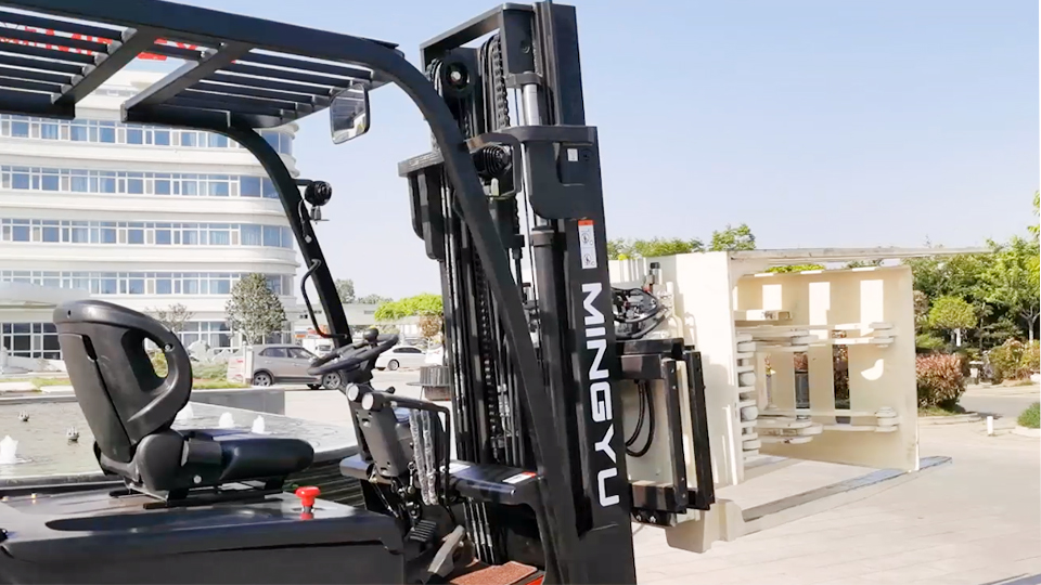
Fork Engagement: The forks must be fully inserted into the pallet or skid. Partial insertion places undue stress on the tip of the forks and creates a cantilevered force that exaggerates the forward shift of the CG.
Back Tilt Application: Before travel, the operator must apply Back Tilt (tilting the mast slightly towards the machine). This action cradles the load against the mast carriage, converting the load's weight from a free-standing mass into an integrated, secured part of the machine's system. This is a primary engineering control against longitudinal instability during deceleration.
B. Travel Height Discipline: The 4-6 Inch Rule
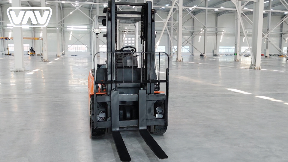
The single most critical procedural control for safe travel is maintaining the correct Load Carry Height.
Rule: The bottom of the forks (or the bottom of the load) should be kept approximately 4 to 6 inches (10-15 cm) above the floor.
Technical Rationale: This rule is a direct attempt to minimize the upward shift of the combined Center of Gravity. Since a higher CG equates to a smaller stability envelope, keeping the load low maximizes the machine’s margin of safety against both lateral and longitudinal tip-overs. Conversely, traveling with the load raised high (e.g., above the mast) is an absolute technical violation, guaranteeing a highly unstable condition.
IV. Execution of Travel: Countering Destabilizing Forces
The act of moving introduces momentum, acceleration, and centrifugal force—all of which act to shift the CG outside the stability triangle. Safe travel procedures are designed to mitigate these dynamic forces.
A. Speed Control and Control Input Modulation
Speed is the primary determinant of safety. A forklift should never exceed a brisk walking pace, especially in congested areas.
Braking and Acceleration: Abrupt starts and stops are major causes of longitudinal tip-over. Rapid acceleration causes the CG to shift backward (creating instability for the load itself), and rapid braking causes a violent forward shift of the CG, pivoting the entire mass over the front axle. Operators must use smooth, modulated control inputs to transition kinetic energy slowly.
Centrifugal Force (Turning): On a turn, the lateral force pushing the load outward ($F_c = \frac{mv^2}{r}$) becomes the primary destabilizing force. This force attempts to push the CG outside the stability base line between the front load wheels. The relationship is exponential: doubling the speed quarters the time available to recover from a skid or tip, while quadrupling the centrifugal force.
B. Steering Dynamics and the "Tail Swing" Hazard
Forklifts steer from the rear axle. This rear-wheel steering configuration results in a unique hazard: tail swing.
When turning, the entire front-end assembly pivots wide while the rear of the machine swings sharply in the opposite direction.
This motion dramatically reduces the machine’s effective stability base during the turn and poses a significant risk to objects, racks, and pedestrians outside the operator's immediate field of vision. All turns, therefore, must be executed slowly and deliberately, anticipating the shift in the CG and the path of the machine's rear.
V. Navigating Hazardous Terrain: Ramps and Inclines
Travel on ramps, grades, or inclines presents the most severe technical challenge, as the angle of the terrain forces a sustained, detrimental shift in the CG.
A. The Golden Rule of Gradient Travel
To maintain longitudinal stability on a gradient, the machine’s orientation must be governed by a single rule: The carried load must always be on the uphill side of the forklift.
Ascending (Traveling Up): The operator drives forward (load in front). The grade pushes the CG backward, but the load's weight maintains pressure on the front wheels, distributing the weight correctly.
Descending (Traveling Down): The operator drives in reverse (load facing up the ramp). If the load were downhill, the combined CG would shift dangerously forward and downward, creating an immediate risk of a longitudinal tip-over forward (known as "pitching").
B. Safety on the Slope
Never Turn: Lateral instability is drastically reduced on a slope. Attempting to turn while ascending or descending shifts the load's weight laterally against the reduced stability base, creating an extremely high risk of a lateral (sideways) tip-over.
Controlled Power: The operator must use continuous, controlled power—never coasting in neutral—to maintain a predictable speed and avoid runaway conditions.
VI. Visibility and Operational Context
When a carried load obstructs the forward line of sight (a common issue with high, square loads), the physics of safety demand a procedural correction:
Reverse Travel Mandate: If the load is too high to provide a clear line of sight, the operator must travel in reverse (with the load trailing). This procedure prioritizes maintaining visibility of the travel path, mitigating the risk of striking pedestrians, racks, or obstacles—a secondary, yet critical, cause of load-related accidents.
Pedestrian Awareness: The interaction between a moving load and surrounding personnel is managed through audible and visual communication. The horn must be sounded at intersections, blind spots, and entry/exit points to account for the machine's limited braking distance, especially with a load.
VII. Conclusion: Technical Compliance and Continuous Training
Safe travel with a carried load on a forklift is not a matter of luck; it is a direct consequence of rigorously adhering to engineering principles designed to manage the machine's dynamic Center of Gravity. The technical controls—from the load center specification on the data plate to the mandated 4-6 inch carry height—must be understood by operators as physical imperatives, not merely suggestions.
Continuous, context-specific training is the final, essential control. Operators must be capable of translating static rules into dynamic, real-time adjustments based on load size, floor condition, and environmental gradients. The margin for error on a loaded forklift is small; absolute technical compliance is the only acceptable standard.
Name: selena
Mobile:+86-13176910558
Tel:+86-0535-2090977
Whatsapp:8613181602336
Email:vip@mingyuforklift.com
Add:Xiaqiu Town, Laizhou, Yantai City, Shandong Province, China
