
vip@mingyuforklift.com
+86-0535-2090977

Introduction
Electric forklifts have become the backbone of modern material handling operations, particularly in indoor environments where emissions, noise, and air quality are critical concerns. Unlike their internal combustion counterparts that rely on diesel, gasoline, or propane engines, electric forklifts harness the power of electrochemical energy storage and electromagnetic conversion to perform the same heavy-duty lifting and transportation tasks. Understanding the working principle behind these machines requires examining how electrical energy is stored, converted, distributed, and ultimately transformed into the mechanical work needed to move thousands of kilograms of cargo. This article provides a comprehensive technical exploration of the systems, components, and processes that make electric forklifts function.
The Power Source: Battery Systems
At the very core of every electric forklift lies its battery system, which serves a dual purpose as both the energy reservoir and a critical structural counterweight. The battery is not merely a fuel tank filled with electrons—it is a complex electrochemical device that determines the forklift's operational range, lifting capacity, and overall performance characteristics.
Battery Chemistry and Configuration
Most electric forklifts utilize lead-acid batteries, which have been the industry standard for decades due to their reliability, cost-effectiveness, and ability to deliver high surge currents. These batteries consist of multiple cells connected in series, with system voltages typically ranging from 24V for smaller pallet trucks to 80V for heavy-duty counterbalance forklifts. Each lead-acid cell produces approximately 2 volts through the electrochemical reaction between lead plates and sulfuric acid electrolyte. When the forklift operates, stored chemical energy is converted into electrical energy through reversible redox reactions at the electrode surfaces.
In recent years, lithium-ion batteries have gained significant traction in the forklift market. Lithium-ion cells offer superior energy density, longer cycle life, faster charging capabilities, and reduced maintenance requirements compared to lead-acid alternatives. A lithium-ion battery pack in a forklift is managed by a sophisticated Battery Management System (BMS) that monitors individual cell voltages, temperatures, and state-of-charge to prevent overcharging, deep discharging, and thermal runaway conditions. This intelligent management allows lithium-ion systems to support opportunity charging—brief charging sessions during breaks and shift changes—rather than requiring the lengthy 7-8 hour charging cycles typical of lead-acid batteries.
Strategic Placement and Counterweight Function
The battery's physical location within the forklift chassis is carefully engineered. Positioned low in the frame, typically beneath the operator's seat or in a dedicated battery compartment, the battery mass contributes significantly to the vehicle's center of gravity. This low placement enhances stability during lifting operations and helps prevent tip-over accidents. In electric forklifts, the battery itself often serves as the primary counterweight, eliminating the need for the heavy cast-iron counterweights found on internal combustion models. The battery's substantial mass—often exceeding 1,000 kilograms in larger models—provides the necessary moment arm to balance loads lifted at the front of the vehicle.
Electric Motor and Drive System
The transformation of electrical energy into mechanical motion occurs within the forklift's electric motor system. This conversion represents the fundamental working principle that distinguishes electric forklifts from their engine-powered equivalents.
Motor Types and Characteristics
Electric forklifts employ either DC (direct current) or AC (alternating current) motors, with the industry trend firmly moving toward AC technology. Traditional DC series-wound motors were favored for their excellent starting torque characteristics and simple speed control through armature voltage regulation. These motors naturally exhibit a "constant power soft characteristic"—meaning they deliver high torque at low speeds (ideal for starting under heavy loads) and maintain consistent power output across a wide speed range. This torque-speed profile closely matches the operational requirements of forklift applications.
Modern electric forklifts increasingly adopt three-phase AC induction motors or permanent magnet synchronous motors. AC motors offer several advantages: higher efficiency (typically 90-95% versus 80-85% for DC motors), reduced maintenance due to the absence of brushes and commutators, better thermal performance, and compatibility with advanced variable frequency drive (VFD) control systems. The VFD converts DC battery power into variable-frequency, variable-voltage AC power, enabling precise speed and torque control while supporting regenerative braking capabilities.
Power Transmission
The motor's rotational output is transmitted to the drive wheels through a mechanical transmission system. Unlike internal combustion forklifts that often require complex multi-speed gearboxes, electric forklifts typically employ simpler single-speed or two-speed transmissions, sometimes utilizing hydrostatic drives. The electric motor's broad torque curve eliminates the need for frequent gear changes, allowing smooth, stepless acceleration and deceleration.
Power flows from the motor through a differential to the drive axle, which distributes torque between the drive wheels while permitting speed differentiation during turns. The drive axle connects to solid rubber or polyurethane tires designed to withstand the high point loads and abrasive conditions of warehouse floors. Some advanced models feature independent wheel motors or all-wheel-drive configurations for enhanced traction on ramps and uneven surfaces.
Electronic Control Systems: The Brain of the Operation
The sophisticated electronic control system serves as the central nervous system of the electric forklift, orchestrating the interaction between operator inputs, power delivery, and safety functions.
Motor Controller and PWM Technology
The motor controller acts as the critical interface between the battery and the drive motor. Modern controllers utilize Pulse Width Modulation (PWM) technology to regulate power flow with exceptional precision. PWM works by rapidly switching power to the motor on and off at frequencies typically ranging from 1 kHz to 20 kHz. By varying the duty cycle—the ratio of "on" time to total cycle time—the controller effectively adjusts the average voltage and current delivered to the motor, thereby controlling speed and torque.
When the operator presses the accelerator pedal, a position sensor (potentiometer or Hall-effect sensor) transmits a signal proportional to pedal displacement to the controller. The controller's microprocessor interprets this input, calculates the appropriate power output based on programmed acceleration curves and load conditions, and generates PWM signals to the power semiconductor switches (IGBTs or MOSFETs) that modulate current to the motor. This closed-loop control ensures smooth, predictable response while protecting the motor from overcurrent, overheating, and stall conditions.
Regenerative Braking
A significant advancement in electric forklift technology is regenerative braking. During deceleration or when traveling downhill, the controller reconfigures the motor to operate as a generator. Instead of consuming electrical power to produce motion, the rotating motor generates electrical power from the vehicle's kinetic energy. This recovered energy is fed back into the battery, effectively extending operational range by 10-20% depending on duty cycle and terrain. Regenerative braking also reduces wear on mechanical brake components, lowering maintenance costs and improving safety through smoother deceleration profiles.
System Integration and Diagnostics
Modern controllers communicate with other vehicle systems via CAN (Controller Area Network) bus architecture. This digital communication network enables real-time data exchange between the motor controller, battery management system, hydraulic control valves, instrument cluster, and external diagnostic equipment. Built-in diagnostic capabilities continuously monitor parameters such as motor temperature, battery voltage, hydraulic pressure, and fault conditions. When anomalies are detected, the system can trigger warning indicators, limit performance, or shut down operations to prevent damage. Error codes stored in the controller's memory facilitate rapid troubleshooting and reduce downtime.
Hydraulic Lifting System
While the electric drive system propels the forklift, the hydraulic system provides the immense mechanical advantage needed to lift and manipulate loads. In electric forklifts, the hydraulic system is powered by an electric motor rather than being mechanically driven by an internal combustion engine.
Hydraulic Power Generation
An electric hydraulic pump motor, separate from the traction drive motor, powers a gear pump or piston pump that pressurizes hydraulic fluid—typically specialized anti-wear oil formulated for high-pressure industrial applications. System pressures commonly range from 10 to 20 MPa (1,450 to 2,900 psi), though heavy-duty applications may exceed these values. The pump motor activates on demand, either through direct operator input or through pressure-sensing controls that start the pump only when hydraulic functions are requested, conserving battery energy.
Valve Control and Actuation
Pressurized hydraulic fluid flows through a multi-way directional control valve manifold that directs flow to specific actuators based on operator commands. The control valve features spools that shift position in response to joystick or lever inputs, opening flow paths to lifting cylinders, tilting cylinders, or auxiliary functions such as side shifters and fork positioners. Proportional valves enable variable flow rates, allowing operators to control lifting and lowering speeds with precision. Load-holding valves prevent uncontrolled descent in the event of hydraulic line failure, while relief valves limit maximum system pressure to protect components from overloading.
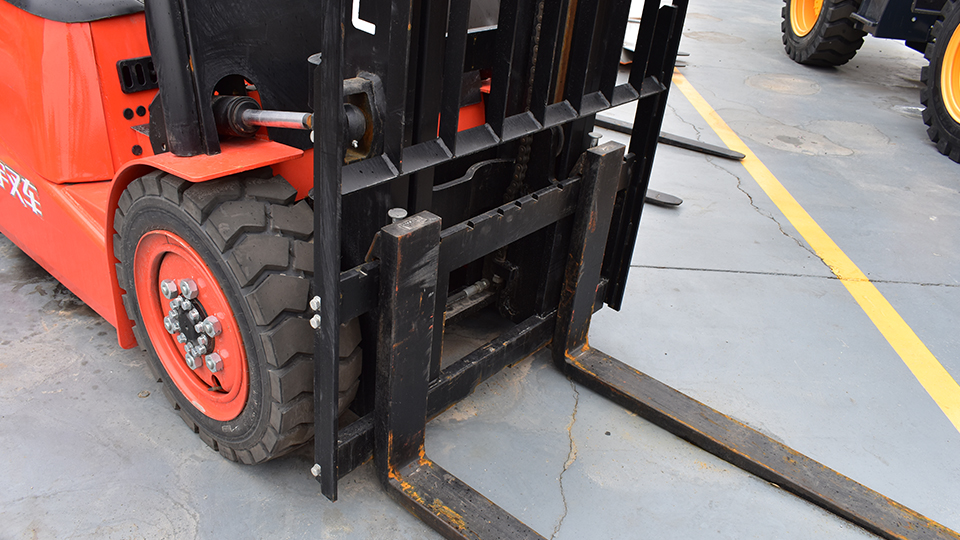
Mast and Lifting Mechanism
The mast assembly represents the mechanical heart of the forklift's lifting capability. Most counterbalance forklifts employ a two-stage or three-stage telescoping mast consisting of nested inner and outer channels. The lifting hydraulic cylinder mounts to the outer mast and extends upward, pushing the inner mast vertically along roller bearings. A critical mechanical advantage is achieved through a chain-and-sprocket arrangement: one end of the lifting chain anchors to the outer mast frame, passes over a sprocket mounted to the top of the inner mast, and attaches to the fork carriage. When the hydraulic cylinder extends at velocity v, the sprocket rises at the same speed, but the chain pull causes the fork carriage to ascend at 2v—effectively doubling the lifting speed relative to cylinder extension while halving the mechanical force requirement. This pulley-like mechanism enables high lift heights without impractically long hydraulic cylinders.
Tilting cylinders, typically mounted at the base of the outer mast, allow the entire mast assembly to pivot forward and backward through angles typically ranging from 3-5 degrees forward and 10-15 degrees backward. Forward tilt facilitates load engagement and deposit, while backward tilt secures loads against the mast during transport, preventing spillage.
Steering and Maneuverability
Electric forklifts predominantly utilize rear-wheel steering configurations, which provide exceptional maneuverability in tight warehouse aisles. The steering system connects the operator's steering wheel to the rear axle through either mechanical linkages with hydraulic power assist or fully electric power steering systems.
In electric power steering configurations, a steering motor responds to torque sensors in the steering column, providing assistive force proportionate to steering effort and vehicle speed. Some advanced systems employ steer-by-wire technology, where the steering wheel operates purely as an input device and a dedicated steering motor controls wheel angle independently. This architecture enables features such as automated guidance, crab steering, and tighter turning radii.
The rear-wheel steering geometry follows Ackermann principles, ensuring that inner and outer wheels trace different radii during turns to minimize tire scrub. Combined with the forklift's compact wheelbase and the instant bidirectional capability of electric drive systems, this steering configuration allows operators to execute tight turns and precise positioning maneuvers in aisles as narrow as 2.5 meters.
Operational Workflow: From Startup to Shutdown
Understanding the working principle of an electric forklift is best appreciated by examining the complete operational sequence:
Initialization Phase: When the operator inserts the key and activates the power switch, the battery connects to the vehicle's low-voltage control circuits. The Electronic Control Unit (ECU) performs a system initialization sequence, verifying sensor functionality, checking battery state-of-charge, and confirming the absence of fault conditions. Instrument displays illuminate, showing battery level, hour meter, and any diagnostic messages.
Driving Operations: The operator selects travel direction using a directional switch or rocker switch. Pressing the accelerator pedal sends an analog signal to the controller, which calculates the required motor torque and generates appropriate PWM signals. The traction motor accelerates smoothly, transferring power through the transmission and differential to the drive wheels. Steering inputs control the rear wheel angle through the steering system, while braking—either through regenerative deceleration upon pedal release or mechanical brake application—slows or stops the vehicle.
Lifting Operations: To engage a load, the operator positions the forks using inching controls (which combine minimal travel speed with precise positioning), then actuates the lift control. The hydraulic pump motor energizes, pressurizing fluid that extends the lifting cylinder and raises the inner mast and fork carriage via the chain mechanism. Tilt controls adjust mast angle for load engagement. Once the load is secured, the operator may raise it to travel height and maneuver to the deposit location.
Load Placement: At the destination, the operator positions the forklift, adjusts mast tilt forward, and gradually lowers the load by releasing hydraulic pressure through the control valve. The load descends under gravity, with flow control valves regulating descent speed to prevent impact. Once the load is deposited, the forks are lowered to travel position, mast is tilted back, and the cycle repeats.
Shutdown: Upon completing operations, the operator engages the parking brake, lowers forks to the ground, and removes the key. Some systems automatically disconnect high-voltage circuits, while others maintain low-power standby modes for accessory functions.
Energy Management and Efficiency Considerations
The working principle of electric forklifts inherently offers superior energy efficiency compared to internal combustion alternatives. Electric motors convert electrical energy to mechanical energy with efficiencies exceeding 90%, while internal combustion engines typically achieve only 25-30% thermal efficiency. Furthermore, electric forklifts eliminate energy losses associated with idling—when stationary, the traction motor consumes negligible power, whereas combustion engines continue burning fuel.
Energy recovery through regenerative braking captures kinetic energy that would otherwise dissipate as heat in mechanical brake systems. Load-sensing hydraulic systems adjust pump output to actual demand rather than maintaining constant pressure, reducing parasitic energy losses. These efficiency advantages translate into lower operating costs, particularly in high-duty-cycle applications where energy consumption dominates total cost of ownership.
Conclusion
The working principle behind an electric forklift represents a sophisticated integration of electrochemical energy storage, electromagnetic energy conversion, electronic power control, and hydraulic force multiplication. From the battery's chemical reactions that store electrical potential, through the motor controller's precise PWM regulation, to the hydraulic system's mechanical advantage in lifting heavy loads, each subsystem contributes to a cohesive material handling solution. As battery technology continues advancing—with higher energy densities, faster charging capabilities, and longer cycle lives—and as motor and control electronics become increasingly efficient and intelligent, electric forklifts are positioned to dominate an ever-expanding range of industrial applications. Understanding these working principles enables operators, maintenance personnel, and fleet managers to optimize performance, extend equipment life, and maximize the operational and environmental benefits that electric forklifts provide.
Name: selena
Mobile:+86-13176910558
Tel:+86-0535-2090977
Whatsapp:8613181602336
Email:vip@mingyuforklift.com
Add:Xiaqiu Town, Laizhou, Yantai City, Shandong Province, China
