
vip@mingyuforklift.com
+86-0535-2090977

Introduction
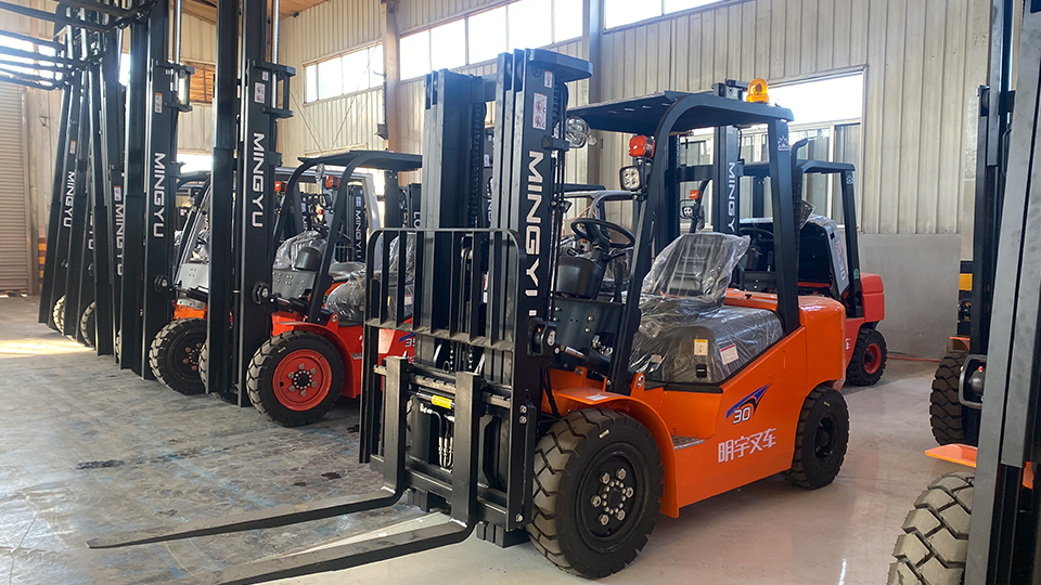
In the bustling environment of warehouses, distribution centers, and manufacturing floors, forklifts serve as the backbone of material handling operations. At the heart of every forklift's lifting prowess lies a sophisticated yet elegantly simple technology: the hydraulic system. This system transforms modest operator inputs into the immense force needed to hoist thousands of pounds of cargo with precision and control.
Understanding forklift hydraulics isn't merely an academic exercise—it's essential for operators, maintenance technicians, and facility managers who depend on these machines for daily operations. This article provides a comprehensive visual and technical breakdown of how forklift hydraulic systems function, from fundamental principles to component-level mechanics.
The Physics of Power: Pascal's Principle in Action
Every forklift hydraulic system operates on Pascal's Principle, a fundamental law of fluid mechanics discovered by Blaise Pascal in the 17th century. The principle states that pressure applied to an enclosed fluid is transmitted undiminished to every portion of the fluid and the walls of the containing vessel.
In practical terms, this means a small force applied to a small piston can generate a massive force at a larger piston, provided the hydraulic fluid transmits the pressure equally throughout the system. For forklift operators, this translates to the ability to lift multi-ton pallets using nothing more than the movement of a control lever or the press of a pedal. The hydraulic system acts as a mechanical amplifier, converting the engine's rotational energy into the linear force that raises and lowers loads.
System Architecture: The Hydraulic Circuit
A forklift hydraulic system is best understood as a closed circuit of power transmission. The system comprises five primary subsystems working in concert: the power generation unit, fluid storage and conditioning, control and distribution, actuation mechanisms, and auxiliary components.
The Power Generation Unit begins with the hydraulic pump, typically driven by the forklift's internal combustion engine or electric motor. This pump draws low-pressure hydraulic fluid from the reservoir and converts mechanical energy into fluid pressure. Common pump types include gear pumps, vane pumps, and piston pumps, each offering different efficiencies and pressure capabilities. The pump's output is measured in gallons per minute (GPM) and determines how quickly the hydraulic cylinders can extend or retract.
Fluid Storage and Conditioning centers on the hydraulic reservoir (tank), which serves multiple functions beyond simple storage. The tank allows air bubbles to escape from the fluid, provides a heat sink for system cooling, and houses filters that remove particulate contaminants. Clean hydraulic fluid is paramount—particles as small as 25 microns can damage precision valve components and accelerate seal wear. Most forklifts employ return-line filters and sometimes pressure-line filters to maintain fluid cleanliness standards.
The Control Center: Valves and Distribution
The hydraulic control valve assembly functions as the system's brain, directing pressurized fluid to specific actuators based on operator input. Modern forklifts typically use multi-way directional control valves configured as monoblock or sectional designs.
Directional Control Valves determine which cylinders receive fluid and in which direction. When an operator pulls the lift lever, the valve shifts to connect the pump output to the rod-end or cap-end of the lift cylinder, while simultaneously opening the opposite port to the return line (tank). This spool valve movement is often actuated manually through cables or linkages, though electro-hydraulic pilot controls are increasingly common in premium equipment.
Pressure Control Valves protect the system from overpressure conditions. The main relief valve limits maximum system pressure—typically set between 2,000 and 3,500 PSI depending on the forklift's capacity. If an operator attempts to lift an overloaded pallet or if a cylinder reaches its mechanical limit, the relief valve opens to divert excess flow back to the tank, preventing catastrophic hose rupture or component damage.
Flow Control Valves regulate the speed of actuator movement by throttling fluid flow. In forklift applications, these may take the form of needle valves or orifice plates that meter flow to the mast tilt cylinders, allowing smooth, controlled tilting of loads regardless of engine speed variations.
The Muscle: Hydraulic Cylinders and Actuators
Hydraulic cylinders represent the business end of the system—the components that convert fluid pressure into the mechanical force visible to operators. Forklifts employ two primary cylinder types: linear actuators for lifting and tilting, and rotary actuators for steering in some designs.
Lift Cylinders are typically double-acting telescopic cylinders mounted within the mast structure. These cylinders feature multiple stages (usually two or three) that nest within each other when retracted, allowing a compact collapsed height while achieving extended lift heights of 15 feet or more. The largest stage (outer barrel) is anchored to the mast, while the smallest stage connects to the carriage and forks. As pressurized fluid enters the cylinder base, it pushes against the piston area, extending the rod and raising the load. The force generated follows the equation F = P × A, where P is system pressure and A is the piston area. A 4-inch diameter cylinder operating at 2,500 PSI generates approximately 31,400 pounds of force—sufficient to lift a 3-ton load while accounting for mechanical advantage losses in the chain pulley system.
Tilt Cylinders are smaller double-acting cylinders mounted between the mast and the forklift chassis. These cylinders control forward and backward tilt of the mast, typically providing 6 to 12 degrees of forward tilt and 10 to 15 degrees of backward tilt. Backward tilt is crucial for load stability during transport, while forward tilt facilitates pallet entry and deposit. The tilt cylinder rods connect to the mast via pivot pins, creating a lever arm that multiplies the cylinder force into the torque needed to tilt loaded masts.
Steering Cylinders in many forklifts, particularly those with rear-wheel steering, use hydraulic power to turn the wheels. A steering orbitrol or valve meters fluid to left and right steering cylinders based on steering wheel input, providing the low-effort turning that allows operators to maneuver in tight warehouse aisles.
The Fluid Highway: Hoses, Pipes, and Fittings
Hydraulic fluid travels through a network of conductors that must withstand high pressure while accommodating the forklift's dynamic movements. Rigid steel tubing handles fixed connections between the valve block and cylinders, while flexible high-pressure hoses—reinforced with braided steel wire—connect moving components like the mast assembly to the chassis. These hoses must resist abrasion from contact with pallets and rack structures while maintaining pressure ratings exceeding the system relief valve setting by a safety factor of at least 4:1.
Quick-disconnect fittings may be present for attachments like side shifters, paper roll clamps, or fork positioners. These auxiliary circuits branch from the main valve block through additional spool sections, allowing the same hydraulic pump to power both mast functions and attachment operations.
Energy Efficiency and Heat Management
Hydraulic systems are remarkably efficient at force multiplication, but they are not without energy losses. Fluid friction within hoses and valves, mechanical friction in cylinders, and pressure drops across orifices all generate heat. In continuous-duty applications, hydraulic fluid temperatures can exceed 180°F, leading to accelerated seal degradation and fluid oxidation.
Forklift hydraulic systems manage heat through reservoir design—tanks are sized to allow sufficient dwell time for heat dissipation—and sometimes through external oil coolers. Fluid viscosity is carefully selected based on operating environment; most manufacturers specify ISO VG 46 hydraulic oil for temperate climates and ISO VG 32 for cold environments to ensure proper flow characteristics at startup.
System Integration: Putting It All Together
The complete operational sequence illustrates the system's integrated functionality. When an operator initiates a lift command:
The engine-driven pump draws fluid from the reservoir, pressurizing it to system pressure (typically 2,000–3,000 PSI)
Pressurized fluid flows to the control valve, where the operator's lever input shifts a spool to connect the pump line to the lift cylinder base port
Fluid enters the cylinder, pushing the piston upward and extending the rod stages
The carriage and forks rise via the chain pulley system, lifting the pallet load
Simultaneously, fluid from the rod side of the cylinder returns to the tank through the valve's return port
When the operator releases the lever, the valve returns to neutral, trapping fluid in the cylinder to hold the load position (with check valves preventing backflow)
To lower the load, the operator pushes the lever in the opposite direction, reversing the flow path and allowing gravity to assist cylinder retraction, with flow restricted by the valve to ensure controlled descent
For tilt operations, the sequence is similar but involves smaller cylinders and typically requires less flow, resulting in slower, more precise movements. The system's modularity allows operators to combine functions—lifting while tilting back, for instance—by manipulating multiple levers simultaneously.
Maintenance Imperatives
Reliable hydraulic performance demands proactive maintenance. Fluid analysis should monitor contamination levels (measured by ISO cleanliness codes), water content, and additive depletion. Seal replacement intervals depend on operating cycles and temperature history, but external leakage at cylinder rods or hose fittings always warrants immediate attention—not merely for fluid conservation, but because leaks indicate potential internal seal failures that could lead to sudden load drops.
Filter elements require replacement at manufacturer-specified intervals or when differential pressure indicators signal clogging. Cavitation—caused by pump inlet restrictions or low fluid levels—produces distinctive whining noises and can destroy pump internals within hours of operation.
Conclusion
Forklift hydraulic systems represent a masterclass in mechanical engineering simplicity. By leveraging the incompressibility of hydraulic fluid and the precision of machined components, these systems enable operators to manipulate loads with forces that would otherwise require massive mechanical linkages. From the pump that generates pressure to the cylinders that perform work, each component plays a vital role in the seamless choreography of material handling.
Understanding these systems at a component level empowers operators to recognize abnormal sounds, pressures, or movements that precede failures. For maintenance professionals, this knowledge facilitates systematic troubleshooting—whether diagnosing a sluggish lift (potential pump wear or internal leakage), erratic tilting (possible valve spool sticking), or creeping descent (likely cylinder seal failure). In an industry where uptime directly correlates with productivity, this technical literacy isn't merely valuable—it's essential.
Name: selena
Mobile:+86-13176910558
Tel:+86-0535-2090977
Whatsapp:8613181602336
Email:vip@mingyuforklift.com
Add:Xiaqiu Town, Laizhou, Yantai City, Shandong Province, China
