
vip@mingyuforklift.com
+86-0535-2090977

The Fulcrum of Safety: A Technical Analysis of the Forklift Load Center
1. Introduction: Defining the Critical Metric
The load center is arguably the most critical variable an authorized Powered Industrial Truck (PIT) operator must understand. It is the fundamental parameter that governs longitudinal (forward/backward) stability and dictates the true maximum lift capacity of any counterbalanced forklift.
Technically, the Load Center (LC) is defined as the horizontal distance measured from the vertical face of the forks (the load backrest) to the load's Center of Gravity (CG).1
This measurement is the linchpin in the seesaw-like balance of the forklift, where the counterweight at the rear is pitted against the load and its moment arm at the front.2 Miscalculating or ignoring the actual load center is the primary mechanism by which a stable truck becomes an unstable lever, leading to forward tip-overs.
2. The Standard Load Center and the Data Plate
2.1 The Manufacturer’s Standard
Every forklift is designed and rated based on a Standard Load Center (SLC), which is the LC distance used by the manufacturer to establish the truck’s maximum rated capacity (the number stamped in large print).3
Common SLCs: The most common SLC is 24 inches (600 mm).4 This standard is derived from the assumption that the load is placed on a standard, symmetrical 48-inch deep pallet, placing the CG precisely at the halfway point (24 inches) from the fork face.5
Regulatory Requirement: OSHA and ANSI B56.1 standards mandate that the official Data Plate (or Nameplate)—a durable metal or decal placard—must display the rated capacity corresponding to this specific Standard Load Center and a maximum lift height.6
2.2 Reading the Data Plate
The data plate is a legally binding contract between the manufacturer and the operator. It contains a critical table or diagram that illustrates the relationship between Load Center and Maximum Capacity.
|
Parameter |
Function |
Metric Example (Standard) |
|
Rated Capacity |
The maximum weight the truck can lift. |
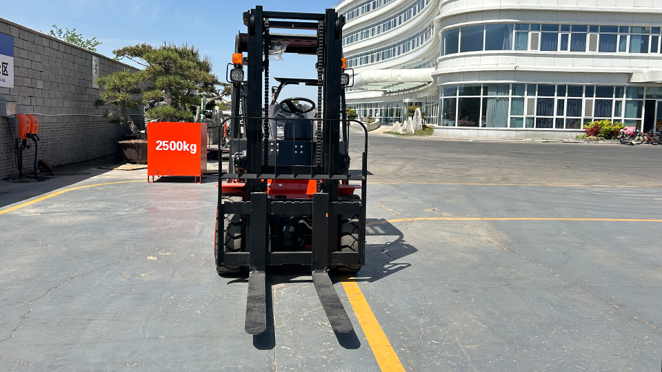
2,500 kg |
|
Standard Load Center |
The distance at which the rated capacity applies (from fork face). |
600 mm (24 in) |
|
Maximum Lift Height |
The mast height at which the capacity is valid. |
5,000 mm |
If the actual load's CG falls farther from the fork face than the SLC listed, the actual lifting capacity of the truck must be derated (reduced).7
3. The Fulcrum Principle and Longitudinal Stability
A counterbalanced forklift operates on the principles of moments and a fulcrum.8
3.1 The Role of the Fulcrum
The fulcrum (the pivot point) for longitudinal stability is the centerline of the front axle’s drive wheels as they contact the ground.9 The entire system is effectively a simple Class 1 lever.
The goal of safe operation is to ensure the Retaining Moment (the downward rotational force created by the truck's weight, including the counterweight) always exceeds the Overturning Moment (the downward rotational force created by the load).
3.2 Calculating the Moments
A moment (10$\mathcal{M}$) is the product of a force (weight, 11$W$) and its perpendicular distance from the fulcrum (distance, 12$D$).13
$$\mathcal{M} = W \times D$$
For a forklift carrying a load, the system's stability is determined by the following inequality:
$$\mathcal{M}_{Retaining} > \mathcal{M}_{Overturning}$$
Where:
Overturning Moment (14$\mathcal{M}_{Load}$): The load weight multiplied by the distance from the front axle (fulcrum) to the load's center of gravity.15
Retaining Moment ($\mathcal{M}_{Truck}$): The combined weight of the truck (including counterweight, engine, operator, etc.) multiplied by the distance from the front axle to the truck's own center of gravity.
When the actual Load Center (LC) is pushed farther out, the distance component (16$D$) of the Overturning Moment increases, causing the Overturning Moment (17$\mathcal{M}_{Load}$) to increase.18 If this moment exceeds the fixed Retaining Moment ($\mathcal{M}_{Truck}$), the front axle pivots, and the truck tips forward.
4. Derating: Calculating Revised Capacity (The Key Technical Step)
When handling a load whose length (and thus its actual Load Center) exceeds the Standard Load Center, the operator must calculate the Revised Capacity (19$\mathcal{C}_{Revised}$) to ensure the Overturning Moment remains safe.20 This process is known as derating.
4.1 The Load Moment Constant
The maximum allowable Overturning Moment is constant and is known as the Load Moment Constant ($\mathcal{M}_{Max}$). It is calculated by multiplying the values from the data plate:
$$\mathcal{M}_{Max} = \mathcal{C}_{Rated} \times (\mathcal{LC}_{Rated} + \mathcal{D}_{Axle})$$
$\mathcal{C}_{Rated}$: Rated Capacity (from data plate).21
$\mathcal{LC}_{Rated}$: Standard Load Center (from data plate).
$\mathcal{D}_{Axle}$: Distance from the vertical face of the forks to the centerline of the front axle (often a fixed specification, but sometimes simplified by the manufacturer's rating).
4.2 The Derating Formula (Simplified for Field Use)
For operational purposes, the maximum safe weight for a New Load Center ($\mathcal{LC}_{New}$) is calculated by maintaining the Load Moment Constant:
$$\mathcal{C}_{Revised} = \frac{\mathcal{C}_{Rated} \times \mathcal{LC}_{Rated}}{\mathcal{LC}_{New}}$$
Example:
Truck Rating: 5,000 lbs at 24 inches.22
Actual Load Center (23$\mathcal{LC}_{New}$): 36 inches (a 72-inch long load).24
$$\mathcal{C}_{Revised} = \frac{5,000 \text{ lbs} \times 24 \text{ in}}{36 \text{ in}} = \frac{120,000}{36} \approx 3,333 \text{ lbs}$$
Technical Conclusion: A load with a 36-inch load center must weigh no more than 3,333 lbs to maintain the stability equivalent of a 5,000 lbs load at the standard 24-inch load center.25 The increase in load center reduced the capacity by 33%.
5. The Stability Triangle and Lateral Stability
While Load Center primarily dictates longitudinal stability (forward tip), it is part of the larger concept of the Stability Triangle, which governs lateral (sideways) stability.
5.1 The Geometry
The stability triangle is an imaginary area on the floor defined by three points of contact between the truck and the ground:26
The center of the rear steer axle (Point A).
The contact point of the right front wheel (Point B).
The contact point of the left front wheel (Point C).
The stability of the forklift is ensured only as long as the Combined Center of Gravity (CG)—the point representing the total weight of the truck, operator, and load—remains within the boundaries of this triangle.27
5.2 Load Center’s Role in Lateral Stability
The Load Center, in conjunction with the placement of the load on the forks, affects the lateral position of the combined CG:
Off-Center Loading: If a load is placed unevenly (e.g., the heaviest boxes are stacked on the right side of the pallet), the combined CG shifts toward that side. While the horizontal Load Center might be 24 inches, the lateral position of the CG moves toward the edge of the stability triangle (line A-B or A-C), increasing the risk of a side tip.
Raised Load: When the mast lifts the load, the entire Combined CG is raised, shifting it closer to the sides of the stability triangle. A higher CG means a greater risk of lateral tip-over, especially during turning or driving on uneven surfaces. This is why loads must be carried as low as possible (4–6 inches off the floor).
6. Conclusion: A Constant Technical Imperative
The forklift load center is not merely a theoretical construct; it is a dynamic safety variable that requires constant assessment and sometimes mathematical calculation by the operator. It dictates the maximum permissible load moment and therefore the safe operating capacity.28
The technical takeaway is clear: Any increase in the Load Center distance requires a reciprocal decrease in the load weight to maintain the stability margins established by the manufacturer and required by safety regulations. By correctly identifying the actual load center and applying the necessary derating, operators ensure the Retaining Moment never succumbs to the Overturning Moment. The integrity of the operation depends on respecting this fundamental physics principle.
Name: selena
Mobile:+86-13176910558
Tel:+86-0535-2090977
Whatsapp:8613181602336
Email:vip@mingyuforklift.com
Add:Xiaqiu Town, Laizhou, Yantai City, Shandong Province, China
