
vip@mingyuforklift.com
+86-0535-2090977

Introduction
The counterbalance forklift represents the most ubiquitous and versatile category of materials handling equipment in industrial operations worldwide. Characterized by its distinctive weight distribution architecture, this powered industrial truck has remained the backbone of warehousing, manufacturing, and logistics operations since the mid-20th century. Unlike specialized variants such as reach trucks or order pickers, the counterbalance forklift derives its name from a fundamental engineering principle: the strategic placement of a substantial mass at the rear of the vehicle to offset the load carried at the front, thereby maintaining dynamic stability during lifting and transportation operations.
Fundamental Design Architecture
The Counterweight System
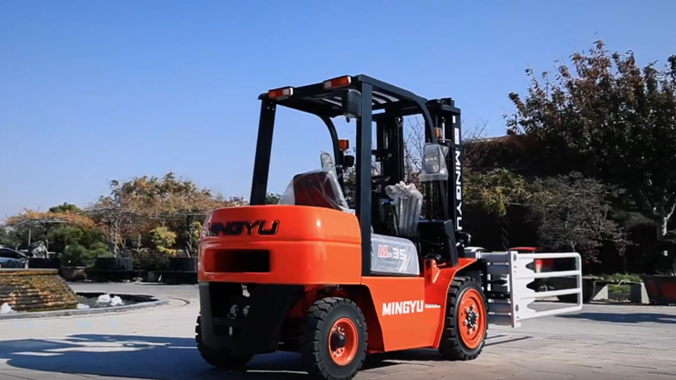
At the heart of every counterbalance forklift lies its namesake component—the counterweight. Typically constructed from cast iron, concrete, or a combination of dense materials, this mass is integrally mounted to the rear chassis of the truck. The counterweight serves a critical dual purpose: it provides the necessary moment force to prevent forward tipping when loads are raised, and it contributes to the overall structural integrity of the vehicle frame.
The physics governing counterweight design follows classical statics principles. When a forklift lifts a load at a given distance from the front wheels (the fulcrum point), it creates a forward tipping moment calculated as the product of load weight and horizontal distance from the fulcrum. The counterweight must generate an equal or greater opposing moment, calculated as counterweight mass multiplied by its distance from the same fulcrum point. Engineers typically incorporate safety factors of 1.5 to 2.0 times the rated load capacity to account for dynamic forces, acceleration effects, and operational tolerances.
Chassis and Frame Construction
The chassis of a counterbalance forklift functions as a stressed-skin structure, integrating the counterweight mounting points, mast attachment locations, and operator compartment into a unified load-bearing framework. Modern forklifts employ high-strength steel alloys with yield strengths exceeding 350 MPa, allowing for optimized weight-to-strength ratios. The frame design must accommodate substantial bending moments during load handling while maintaining dimensional stability for mast alignment precision.
The wheelbase configuration distinguishes counterbalance forklifts from other industrial truck categories. With a wheelbase typically ranging from 1,200 mm to 2,500 mm depending on capacity class, the design prioritizes longitudinal stability over maneuverability. The rear axle, often mounted on a pivoting suspension system, maintains ground contact across uneven surfaces while the rigid front axle carries the primary vertical loads.
The Mast and Lifting Mechanism
Structural Components
The mast assembly constitutes the most visually prominent feature of a counterbalance forklift, comprising nested channel sections that telescope to achieve variable lift heights. Standard two-stage masts (duplex) provide lift ranges from 3,000 mm to 4,500 mm, while three-stage masts (triplex) extend operational reach to 6,500 mm or greater. Quad-stage masts enable extreme lift heights exceeding 10,000 mm for specialized high-bay warehousing applications.
Mast construction utilizes high-strength rolled steel channels with integrated roller or bushing guidance systems. The inner channels (carriage channels) support the fork carriage assembly, while outer channels attach to the chassis frame. Hydraulic cylinders, typically positioned within the mast structure or externally mounted, provide lifting force through pressurized hydraulic fluid, usually operating at pressures between 15 and 25 MPa.
Hydraulic System Architecture
The hydraulic system represents a critical subsystem integrating multiple functions: main lift, auxiliary tilt, and optional side-shift or attachment control. A gear-type or piston-type hydraulic pump, driven by the prime mover (internal combustion engine or electric motor), generates system pressure. Control valves direct fluid flow to specific actuators based on operator input through mechanical linkages or electronic controls.
The tilt mechanism, essential for load retention and deposit operations, typically provides 6 to 12 degrees of backward tilt and 3 to 5 degrees of forward tilt. This angular adjustment capability compensates for mast deflection under load and enables precise load positioning. Side-shift attachments, increasingly common in modern configurations, allow lateral carriage adjustment of 100 to 150 mm without truck repositioning, significantly enhancing operational efficiency in confined spaces.
Powertrain Configurations
Internal Combustion Variants
Counterbalance forklifts traditionally employed internal combustion engines, with diesel, gasoline, and liquid petroleum gas (LPG) representing the primary fuel options. Diesel-powered units dominate outdoor and heavy-duty applications, offering superior torque characteristics and fuel efficiency for capacities exceeding 5,000 kg. LPG configurations provide cleaner combustion suitable for indoor operations with adequate ventilation, while gasoline engines find limited application in specialized markets.
Modern internal combustion engines incorporate electronic fuel injection, exhaust gas recirculation, and diesel particulate filters to meet stringent emissions standards. Engine power outputs range from 25 kW for compact 1,500 kg capacity units to over 100 kW for heavy-duty 10,000 kg capacity trucks.
Electric Propulsion Systems
Electric counterbalance forklifts have experienced substantial market penetration growth, driven by environmental regulations, operational cost considerations, and technological advancement. Lead-acid batteries historically dominated the sector, offering proven reliability and established recycling infrastructure. However, lithium-ion battery technology has emerged as the preferred solution for new installations, providing energy density improvements of 50-100%, opportunity charging capability, and elimination of battery maintenance requirements.
Electric drivetrains typically employ AC induction motors or permanent magnet synchronous motors for traction, with rated outputs from 5 kW to 30 kW depending on application requirements. Regenerative braking systems recover kinetic energy during deceleration, extending operational range and reducing brake wear. The elimination of exhaust emissions and substantial reduction in noise levels (typically 10-15 dB lower than equivalent IC units) enables electric forklifts to operate in sensitive environments including food processing, pharmaceuticals, and retail operations.
Stability Dynamics and Safety Engineering
The Stability Triangle Concept
The operational safety of counterbalance forklifts fundamentally depends upon maintaining the combined center of gravity within a defined stability envelope. This theoretical construct, termed the "stability triangle," connects the front drive wheels (forming the base) with the pivot point of the rear steer axle (forming the apex). The forklift remains stable provided the vertical projection of the combined truck and load center of gravity falls within this triangular boundary.
As load is raised vertically, the center of gravity shifts forward proportionally. Simultaneously, mast back-tilt shifts the center of gravity rearward, partially compensating for the elevation effect. However, at maximum lift height with forward tilt, the combined center of gravity approaches the forward edge of the stability triangle, creating the maximum tipping risk condition. This explains the strict operational prohibition against elevated travel and the emphasis on maintaining minimal mast tilt during movement.
Load Capacity Ratings and Derating Factors
Manufacturers specify rated load capacities at defined load centers, typically 500 mm or 600 mm from the fork face. This standardized measurement represents the horizontal distance from the vertical face of the forks to the center of gravity of a uniformly distributed cubic load. Non-uniform loads, extended load centers due to attachments, or elevated lift heights necessitate capacity derating to maintain stability margins.
The capacity rating plate, permanently affixed to every forklift, provides critical operational parameters including maximum lift height ratings, load center limitations, and attachment-specific capacity reductions. Operators must understand that capacity decreases non-linearly with increasing load center—a load with a 1,000 mm center of gravity exerts twice the tipping moment of an equivalent weight at 500 mm, potentially reducing safe capacity by 50% or more.
Operational Applications and Configurations
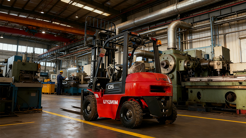
Standard Warehouse Operations
Counterbalance forklifts excel in applications requiring versatile load handling across variable distances and surface conditions. Unlike reach trucks confined to narrow aisles or pallet trucks limited to horizontal transport, counterbalance configurations provide comprehensive functionality: loading/unloading trailers, stacking in rack systems up to 9,000 mm, and transporting loads across irregular surfaces including gravel, asphalt, and concrete expansion joints.
The standard configuration accommodates attachments including carton clamps, paper roll clamps, push-pull systems, and rotators, enabling handling of non-palletized loads. This adaptability explains the counterbalance forklift's prevalence in general manufacturing, beverage distribution, and third-party logistics operations where load diversity precludes specialized equipment deployment.
Specialized Variants
Container handling operations utilize high-capacity counterbalance forklifts with specialized mast configurations and enhanced cooling systems for tropical environments. Explosion-proof variants incorporate flameproof enclosures, intrinsically safe electrical systems, and surface temperature limitations for hazardous area classification zones.
Rough-terrain counterbalance forklifts feature enlarged pneumatic tires, increased ground clearance, and four-wheel-drive capability for construction sites, lumber yards, and agricultural applications. These specialized units sacrifice some load capacity and lift height for enhanced mobility across unprepared surfaces.
Ergonomic and Technological Integration
Operator Interface Design
Modern counterbalance forklifts incorporate substantial ergonomic engineering to reduce operator fatigue and enhance safety. Adjustable suspension seats with weight compensation, reduced-vibration mounting systems, and low-effort hydraulic controls minimize physical stress during extended shifts. The operator compartment layout follows anthropometric principles, positioning controls within optimal reach envelopes and providing unobstructed visibility to the load, forks, and travel path.
Advanced Safety Systems
Technological integration has substantially enhanced counterbalance forklift safety and efficiency. Load moment indicators (LMI) utilize strain gauges and inclination sensors to calculate real-time stability margins, providing visual and audible warnings as operational limits approach. Speed-sensitive steering systems reduce rear axle swing at elevated travel speeds, enhancing directional stability.
Telematics systems enable fleet management optimization through operational data collection: utilization rates, impact detection, maintenance scheduling, and operator performance metrics. Automated guidance systems, including wire-guided and laser-guided variants, enable semi-autonomous operation in high-throughput distribution centers.
Maintenance and Lifecycle Considerations
Preventive Maintenance Protocols
Counterbalance forklift reliability depends upon systematic maintenance addressing mechanical, hydraulic, and electrical subsystems. Engine-powered units require scheduled oil analysis, filter replacement, and valve adjustment. Electric configurations demand battery maintenance including electrolyte level monitoring (lead-acid), thermal management system verification, and contactor inspection.
Hydraulic system maintenance focuses on fluid cleanliness—contamination control through filtration maintenance prevents premature component wear in pumps, valves, and cylinders. Mast roller and bushing inspection ensures smooth elevation operation and prevents channel binding under load.
Total Cost of Ownership Analysis
Acquisition cost represents only a fraction of counterbalance forklift lifecycle expenditure. Electric configurations typically demonstrate lower total cost of ownership in intensive indoor applications despite higher initial capital investment, through reduced energy costs, eliminated engine maintenance, and extended component lifespans. Internal combustion variants retain economic advantages in outdoor, intermittent-duty, or heavy-capacity applications where battery technology limitations apply.
Residual value considerations favor established manufacturers with comprehensive service networks and parts availability. Standardized components across model ranges reduce parts inventory requirements and simplify technical training for maintenance personnel.
Conclusion
The counterbalance forklift embodies a mature yet continuously evolving technology, representing the convergence of mechanical engineering, hydraulic systems, and modern control electronics. Its fundamental operating principle—the strategic counterweight placement enabling front-loaded stability—has proven adaptable across six decades of materials handling evolution. While specialized equipment addresses specific operational niches, the counterbalance configuration retains unmatched versatility for general industrial applications.
Current development trends emphasize electrification, automation integration, and enhanced safety systems, positioning the counterbalance forklift for continued relevance in increasingly sophisticated supply chain operations. Understanding the technical principles underlying counterbalance forklift design enables informed equipment selection, safe operation, and optimized fleet management—essential competencies for modern materials handling professionals.
Name: selena
Mobile:+86-13176910558
Tel:+86-0535-2090977
Whatsapp:8613181602336
Email:vip@mingyuforklift.com
Add:Xiaqiu Town, Laizhou, Yantai City, Shandong Province, China
